In our power plants, many RTD sensors are used to monitor temperature in several locations. At least twelve sensors here. Each of them delivers temperature reading to CRT (yeah, it's too old but it's ok :D). The connection diagram is looked like this picture below.
We use Pt50 and I think it should be change to Pt100 since Pt50 is not ordinary used by now. Well, our power plants has a 20th century's technology. Actually, the cable from sensors to transducer is long enough (more than 10 meters) so it has a compensation of transducer reading in ohms.
To callibrate the system, we should have the following devices :
- Ohm meter and ampere meter, or AVO-meter to check the resistance and output current
- Precision sliding resistor to give nominal resistance we need
- Transducer holder, it usually comes with its transducer's box
- Some cable for wiring
- Power supply to energize the transducer
- Trimmer to trim span and zero of the transducer
Now we're ready to callibrate. First of all, don't forget to make a resistance table consists of resistance versus temperature reading of Pt50. I use the Callendar-Van Dusen equation below :
R(t) = R(0) [1 + At + Bt2]
where A = 3.9083.10-3 °C-1, B = -5.775.10-7 °C-2, R(0) = 50 Ω, and t = temperature in °C. The result is shown in table below :
From the transducer label, we can find many useful information i.e. pin connection number of the holder, the source that is used, input, and output of transducer. For CGP-2M (temperature transducer for Pt50) we can see that it has 0 - 150 °C (pin 3-4-5) correspond to 4 - 20 mA DC output (pin 1(+) and 2 (-)) and AC 100-110 V (pin 7-8). For our need, pin 4-5 can be shorted since pin 5 is used for compensation (it's relatively too small). So the connection diagram will look like this :
Determine the ZERO
Set the sliding resistor to have a resistance of 50 Ω as close as possible. Check it by a precision ohm meter on end point of cable. The cable also have a resistance itself. So 50 Ω is summation of sliding resistor and cables. Connect the cable from sliding rhesistor to transducer holder. Turn on the power supply and read the transducer output. It shold be read 4.00 mA. If it is not, turn the zero trimpot right or left carefully to get 4.00 mA reading. Congratulation, you have set the zero point for transducer.
Determine SPAN
Turn off power supply and unplug transducer to release resistance cable. Set the resistance to 78.66 Ω correspond to 150 °C which gives 20.00 mA output of transducer. Repeat the same procedure as determining zero. The difference is now amperemeter reading should be 20.00 mA. Turn span trimpot right or left to get 20.00 reading.
You can check the transducer output using varied resistance to see it has a linear output or not. If it is not, find the closest linear reading of transducer to your daily reading. So if it is used to monitor a daily temperature of bearing around 50 - 60 °C, make sure the transducer reading in this range is linear. But, you must make a note that this transducer should be retired off soon.
Checking the system
We have callibrate all transducer and the result is good. Now we have to check whole temperature system. It means from sensor that placed far away to the nominal shown in CRT. We need a good temperature callibrator to give a certain heat so that the sensor read the same or quiet same temperature all the time. For example, we use Ametek Jofra - Temperature Callibrator.
First of all, place the sensor, cable, and transducer in right place. After setting the temperature to Ametek - where there is sensor in it - we have to wait until the temperature shown in Ametek is steady. We can use other thermometer to compare the temperature in Ametek. Just to make sure.
When temperature is steadily set, read the nominal in CRT. It's usually different between the actual and the nominal. It can be considered since we have more than 10 meters cable connecting sensor to transducer which give certain resistance donated to total resistance reading of transducer. In earlier step we've sure that our transducer is linear. So all we can do is turn the trimpot for span to equalize the actual temperature and nominal reading in CRT. It is ok since the acceptable error reading is 2 °C.
Callibrating RTD Sensors
Thursday, April 14, 2011
Labels:
callibration,
RTD,
sensors,
temperature
0
comments
![]()
Bimetallic Thermometers
Saturday, May 22, 2010
The Principle
Regarding to www.howstuffworks.com, the principle behind a bimetallic strip thermometer relies on the fact that different metals expand at different rates as they warm up. By bonding two different metals together, you can make a simple electric controller that can withstand fairly high temperatures. This sort of controller is often found in ovens. It is shown in the diagram below.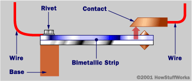
Two metals make up the bimetallic strip (hence the name). In this diagram, the green metal would be chosen to expand faster than the blue metal if the device were being used in an oven. In a refrigerator, you would use the opposite setup, so that as the temperature rises the blue metal expands faster than the green metal. This causes the strip to bend upward, making contact so that current can flow. By adjusting the size of the gap between the strip and the contact, you control the temperature.
You will often find long bimetallic strips coiled into spirals. This is the typical layout of a backyard dial thermometer. By coiling a very long strip it becomes much more sensitive to small temperature changes. In a furnace thermostat, the same technique is used and a mercury switch is attached to the coil. The switch turns the furnace on and off.
How to Calibrate
There are two common ways to calibrate this kind of sensor, the ice and boiling method.
The Ice Method
Immerse the temperature probe at least two inches into a glass of finely crushed ice. Add cold tap water to remove air pockets. Wait at least 1 minute. The gauge should read 32 degrees F or 0 degree C. If it does not, turn the adjustment nut on the back of the reading dial with a pair of pliers until the dial reads 32 degrees F or 0 degree C. Wait at least 1 minute to verify correct adjustment.
The Boiling Method
Submerge the probe into boiling water. Wait until the needle stops moving, then adjust the calibration nut until the dial reads 212 degrees F or 100 degrees C. Since the boiling point of water decreases as altitude increases, this method may not be as accurate as the ice method at altitudes above sea level unless the exact boiling point temperature is known.
Advantage and Disadvantage
Advantages of bimetallic devices are its portability and independence from a power supply. It also can be directly used for automatic on-off switch based on temperature increasing. The simple sample is an automatic iron and food processing devices (e.g. microwave, oven, toaster, etc).
However, they are not usually quite as accurate as are electrical devices, and you cannot easily record the temperature value as with electrical devices like thermocouples or RTDs. It also need to be calibrated frequently to make sure of its accuracy.
Labels:
bimetal,
calibrate,
sensors,
temperature,
thermal
2
comments
![]()